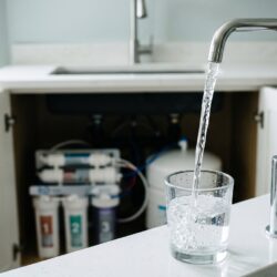
If your water distribution loop is designed with a single static branch, you aren’t running a lab; you are running a high-end bacteria farm.
Proper water distribution loop design is the only way to ensure that the ultrapure water leaving your polisher actually reaches your analytical instruments without picking up a lethal dose of organic or microbial hitchhikers.

As a consultant who has audited over 200 pharmaceutical and clinical facilities, I can confirm that 90% of water quality failures happen in the pipes, not the purification unit. Mastering this infrastructure ensures your lab remains compliant with USP and ASTM standards while protecting your most expensive equipment.
But most facility engineers prioritize “easy plumbing” over “fluid dynamics.”
That single convenience valve at the end of a long hallway is currently destroying your data.
The Danger of Stagnation
Stagnation is the primary catalyst for biofilm formation in any high purity water system. When water velocity drops below a critical threshold, typically 0.9 to 1.2 meters per second, it allows planktonic bacteria to adhere to the interior pipe walls.
Once attached, these organisms secrete extracellular polymeric substances (EPS) that create a protective matrix, shielding them from chemical sanitization and UV exposure. This mechanism converts a clean pipe into an active source of Total Organic Carbon (TOC) and endotoxin contamination.
The real world symptom of this failure is a chronic, low-level rise in TOC that persists even after you replace your purification cartridges. If you ignore this, the biofilm will eventually “slough off,” sending massive bursts of bacteria into your LC-MS or cell culture media, leading to failed assays and costly investigations. In clinical settings, this violates ISO 13485 risk management protocols.
- Flow Velocity: Maintain a minimum of 3 feet per second (fps) in the return line.
- Reynolds Number: Target turbulent flow (Re > 4000) to ensure effective scrubbing of pipe walls.
- TOC Thresholds: Levels should remain below 500 ppb for USP <643> compliance.
Without constant movement, your ultrapure water begins a rapid slide toward non-potable quality.
Principles of Dead Leg Removal
A “dead leg” is any area of piping where water can sit for more than 24 hours without being replaced by the main flow. The industry standard, often cited in WHO Technical Report Series 970, is the “3D Rule.” This rule states that the length of a stagnant branch should not exceed three times the diameter of the main header pipe. The mechanism is simple: if the branch is too long, the kinetic energy from the main loop cannot penetrate the branch to keep the water fresh.
In practice, this means your T-junctions must be as tight as possible to the point of use. If a drop-leg to a bench is 4 feet long but only used once a week, it acts as a reservoir of contamination that bleeds back into the main loop every time the pump cycles. The consequence is erratic “ghost peaks” in chromatography that appear only on Monday mornings after a weekend of stagnation.
| Condition | Acceptable Ratio | Risk Level |
|---|---|---|
| Ideal Design | < 2D | Negligible |
| Regulatory Max | 3D | Moderate |
| Critical Failure | 6D | High (Biofilm certain) |
Eliminating these pockets of rot is the only way to ensure your 4-step process for lab purity actually works.
Sanitary Piping Materials
The material of your pipes is just as important as the direction of the flow. For recirculating water systems, you must use materials that are non-leaching and have an ultra-smooth internal surface (low Ra value). Pigmented Polypropylene (PP) or Polyvinylidene Fluoride (PVDF) are the gold standards because they are joined using infrared or butt-fusion welding, which eliminates the crevices found in threaded or glued joints.
The mechanism of contamination in low-grade piping involves “leaching and lodging.” Standard PVC pipes use solvent glues that leach organic carbon into the water for months, while rough interior surfaces provide “hooks” for bacteria to grab onto. Stainless steel (316L) is an alternative, but it requires orbital welding and passivating with nitric acid to prevent iron leaching, which can interfere with sensitive ICP-MS applications.
Selecting the wrong material can result in metal ion interference or elevated TOC, which is why we cover these choices in our medical grade water guide. If you use the wrong pipe, you are fighting an uphill battle against your own infrastructure.
Auditing Your Lab Facility Plumbing
Auditing an existing loop requires a “detective” mindset to find hidden stagnant points. Start by mapping the entire loop from the storage tank through every sub-loop and back to the return. You are looking for capped valves, abandoned sinks, or bypass lines that were installed “just in case” but are never used. These are the primary sites for bacterial colonization that can seed the rest of your facility.
The audit mechanism involves measuring the temperature and TOC at the furthest point of the loop versus the storage tank. If the temperature in the return line rises more than 5 degrees Celsius, your flow is too slow. If the TOC at a specific tap is 20% higher than the tank, you have a local contamination source. Failing to perform this audit annually can lead to a “systemic crash” where the entire loop must be shut down for a 24-hour chlorine or peracetic acid shock treatment.
- Audit Step 1: Physical walk-through to label every dead leg.
- Audit Step 2: Flow rate verification at the return manifold.
- Audit Step 3: Sampling at “worst-case” points during low-usage hours.
Does your current facility map show every valve, or are you operating on guesswork?
Implementing Zero-Static Valves
The final piece of a world-class loop is the zero-static valve. Unlike a standard ball valve, which has a “dead zone” around the ball when closed, a zero-static diaphragm valve is designed so the seal happens directly at the wall of the main pipe. This mechanism ensures that the water in the loop is always “scrubbing” the valve face, preventing any water from sitting still.
Real-world lab symptoms of using cheap valves include “first-liter” contamination, where the first bottle of water you draw is significantly dirtier than the second. This happens because the water trapped in the valve body has turned into a bacterial soup. Using high-purity diaphragm valves reduces this risk to nearly zero.
The Criticality of Constant Recirculation
A water loop that shuts off at night is a disaster waiting to happen. The mechanism of protection in a recirculating system relies on constant movement through UV sterilization and sub-micron filtration. When the pumps stop, the water temperature rises and the UV oxidation ceases, creating a perfect incubator for any bacteria that survived the last sanitization cycle. This results in a “Monday Morning Spike” where TOC and microbial counts exceed USP limits before the first sample is even injected.
Modern systems should use Variable Frequency Drives (VFDs) to reduce pump speed during off-hours while maintaining a minimum velocity of 0.9 meters per second. This saves energy without compromising the hydraulic integrity of the loop. If your system is not running 24/7, you are essentially starting a new, uncontrolled contamination experiment every single evening.